Module 3
RTOS and IDE for Embedded System Design:
Operating System basics, Types of operating systems, Task, process and threads (Only POSIX Threads with an example program), Thread pre-emption, Preemptive Task scheduling techniques, Task Communication, Task synchronization issues – Racing and Deadlock, how to choose an RTOS, Integration and testing of Embedded hardware and firmware, Embedded system Development Environment – Block diagram (excluding Keil).
Operating System Basics:
The Operating System acts as a bridge between the user applications/tasks and the underlying system resources through a set of system functionalities and services OS manages the system resources and makes them available to the user applications/tasks on a need basis
The primary functions of an Operating system are
- Make the system convenient to use
- Organize and manage the system resources efficiently and correctly
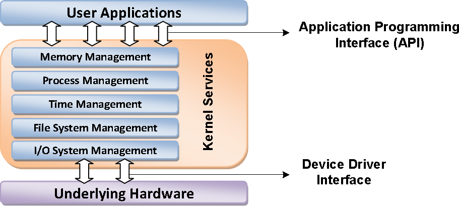
Fig. The Operating System Architecture
Following are some of important functions of an operating System.
- Memory Management Processor Management Device Management File Management Security
 Control over system performance Job accountingError detecting aids Coordination between other software and users


An Operating System provides services to both the users and to the programs. It provides programs an environment to execute.
- It provides users the services to execute the programs in a convenient manner.
- Following are a few common services provided by an operating system: Program execution
- I/O operations
- File System manipulation
The Kernel
The kernel is the core of the operating system. It is responsible for managing the system resources and the communication among the hardware and other system services. Kernel acts as the abstraction layer between system resources and user applications.
Kernel contains a set of system libraries and services. For a general purpose OS, the kernel contains different services like
- Process Management
- Primary Memory Management
- File System management
- I/O System (Device) Management
- Secondary Storage Management
- Protection
- Time management
- Interrupt Handling
Process Management:
- A program does nothing unless their instructions are executed by a CPU.A process is a program in execution. A time shared user program such as a complier is a process. A word processing program being run by an individual user on a pc is a process.
- A system task such as sending output to a printer is also a process. A process needs certain resources including CPU time, memory files & I/O devices to accomplish its task.
- These resources are either given to the process when it is created or allocated to it while it is running. The OS is responsible for the following activities of process management.
- Creating & deleting both user & system processes.
- Suspending & resuming processes.
- Providing mechanism for process synchronization.
- Providing mechanism for process communication.
- Providing mechanism for deadlock handling.
Main Memory Management:
The main memory is central to the operation of a modern computer system. Main memory is a large array of words or bytes ranging in size from hundreds of thousand to billions. Main memory stores the quickly accessible data shared by the CPU & I/O device. The central processor reads instruction from main memory during instruction fetch cycle & it both reads
&writes data from main memory during the data fetch cycle. The main memory is generally the only large storage device that the CPU is able to address & access directly. For example, for the CPU to process data from disk. Those data must first be transferred to main memory by CPU generated E/O calls. Instruction must be in memory for the CPU to execute them. The OS is responsible for the following activities in connection with memory management.
- Keeping track of which parts of memory are currently being used & by whom.
- Deciding which processes are to be loaded into memory when memory space becomes available.
- Allocating &deal locating memory space as needed.
File Management:
File management is one of the most important components of an OS computer can store information on several different types of physical media magnetic tape, magnetic disk & optical disk are the most common media. Each medium is controlled by a device such as disk drive or tape drive those has unique characteristics. These characteristics include access speed, capacity, data transfer rate & access method (sequential or random).For convenient use of computer system the OS provides a uniform logical view of information storage. The OS abstracts from the physical properties of its storage devices to define a logical storage unit the file. A file is collection of related information defined by its creator. The OS is responsible for the following activities of file management.
- Creating & deleting files.
- Creating & deleting directories.
- Supporting primitives for manipulating files & directories.
- Mapping files into secondary storage.
- Backing up files on non-volatile media.
I/O System Management:
One of the purposes of an OS is to hide the peculiarities of specific hardware devices from the user. For example, in UNIX the peculiarities of I/O devices are hidden from the bulk of the OS itself by the I/O subsystem. The I/O subsystem consists of:
- A memory management component that includes buffering, catching & spooling.
- A general device- driver interfaces drivers for specific hardware devices. Only the device driver knows the peculiarities of the specific device to which it is assigned.
Secondary Storage Management:
The main purpose of computer system is to execute programs. These programs with the data they access must be in main memory during execution. As the main memory is too small to accommodate all data & programs & because the data that it holds are lost when power is lost. The computer system must provide secondary storage to back-up main memory. Most modern computer systems are disks as the storage medium to store data & program. The operating system is responsible for the following activities of disk management.
- Free space management.
- Storage allocation.
- Disk scheduling
Because secondary storage is used frequently it must be used efficiently.
Networking:
A distributed system is a collection of processors that don’t share memory peripheral devices or a clock. Each processor has its own local memory & clock and the processor communicate with one another through various communication lines such as high speed buses or networks. The processors in the system are connected through communication networks which are configured in a number of different ways. The communication network design must consider message routing & connection strategies are the problems of connection & security.
Protection or security:
If a computer system has multi users & allow the concurrent execution of multiple processes then the various processes must be protected from one another’s activities. For that purpose, mechanisms ensure that files, memory segments, CPU & other resources can be operated on by only those processes that have gained proper authorization from the OS.
Interrupt Handling
Kernel provides handler mechanism for all external /internal interrupts generated by the system. These are some of the important services offered by the kernel of an operating system. It does not mean that a kernel contains no more than components/ services or more number
of components/services.
Kernel Space and User Space
- The program code corresponding to the kernel applications/services are kept in a contiguous area (OS dependent) of primary (working) memory and is protected from the un-authorized access by user programs/applications
- The memory space at which the kernel code is located is known as ‘Kernel Space’
- All user applications are loaded to a specific area of primary memory and this memory area is referred as ‘User Space’
- The partitioning of memory into kernel and user space is purely Operating System dependent
- An operating system with virtual memory support, loads the user applications into its corresponding virtual memory space with demand paging technique
- Most of the operating systems keep the kernel application code in main memory and it is not swapped out into the secondary memory
Monolithic Kernel
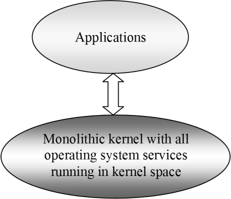
- All kernel services run in the kernel space
- All kernel modules run within the same memory space under a single kernel thread
- The tight internal integration of kernel modules in monolithic kernel architecture allows the effective utilization of the low-level features of the underlying system
- The major drawback of monolithic kernel is that any error or failure in any one of the kernel modules leads to the crashing of the entire kernel application
- LINUX, SOLARIS, MS-DOS kernels are examples of monolithic kernel
Microkernel
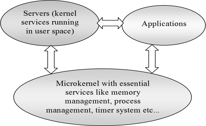
- The microkernel design incorporates only the essential set of Operating System services into the kernel
- Rest of the Operating System services are implemented in programs known as ‘Servers’ which runs in user space
- The kernel design is highly modular provides OS-neutral abstraction
- Memory management, process management, timer systems and interrupt handlers are examples of essential services, which forms the part of the microkernel
- QNX, Minix 3 kernels are examples for microkernel
Types of Operating Systems:
Depending on the type of kernel and kernel services, purpose and type of computing systems where the OS is deployed and the responsiveness to applications, Operating Systems are classified into
General Purpose Operating System (GPOS)
- Operating Systems, which are deployed in general computing systems
- The kernel is more generalized and contains all the required services to execute generic applications
- Need not be deterministic in execution behavior
- May inject random delays into application software and thus cause slow responsiveness of an application at unexpected times
- Usually deployed in computing systems where deterministic behavior is not an important criterion
- Personal Computer/Desktop system is a typical example for a system where GPOSs are deployed.
- Windows XP/MS-DOS etc are examples of General Purpose Operating System
Real Time Purpose Operating System (RTOS)
- Operating Systems, which are deployed in embedded systems demanding real-time response
- Deterministic in execution behavior. Consumes only known amount of time for kernel applications
- Implements scheduling policies for executing the highest priority task/application always
- Implements policies and rules concerning time-critical allocation of a system’s resources
- Windows CE, QNX, VxWorks MicroC/OS-II etc are examples of Real Time Operating Systems (RTOS
The Real Time Kernel
The kernel of a Real Time Operating System is referred as Real Time kernel. In complement to the conventional OS kernel, the Real Time kernel is highly specialized and it contains only the minimal set of services required for running the user applications/tasks. The basic functions of a Real Time kernel are
- Task/Process management
- Task/Process scheduling
- Task/Process synchronization
- Error/Exception handling
- Memory Management
- Interrupt handling
- Time management
Task/Process Management
Deals with setting up the memory space for the tasks, loading the task’s code into the memory space, allocating system resources, setting up a Task Control Block (TCB) for the task and task/process termination/deletion. A Task Control Block (TCB) is used for holding the information corresponding to a task. TCB usually contains the following set of information
- Task ID: Task Identification Number
- Task State: The current state of the task. (E.g. State= ‘Ready’ for a task which is ready to execute)
- Task Type: Task type. Indicates what is the type for this task. The task can be a hard real time or soft real time or background task.
- Task Priority: Task priority (E.g. Task priority =1 for task with priority = 1)
- Task Context Pointer: Context pointer. Pointer for context saving
- Task Memory Pointers: Pointers to the code memory, data memory and stack memory for the task
- Task System Resource Pointers: Pointers to system resources (semaphores, mutex etc) used by the task
- Task Pointers: Pointers to other TCBs (TCBs for preceding, next and waiting tasks)
- Other Parameters Other relevant task parameters
- The parameters and implementation of the TCB is kernel dependent. The TCB parameters vary across different kernels, based on the task management implementation
- Task/Process Scheduling: Deals with sharing the CPU among various tasks/processes. A kernel application called ‘Scheduler’ handles the task scheduling. Scheduler is nothing but an algorithm implementation, which performs the efficient and optimal scheduling of tasks to provide a deterministic behavior.
- Task/Process Synchronization: Deals with synchronizing the concurrent access of a resource, which is shared across multiple tasks and the communication between various tasks.
- Error/Exception handling: Deals with registering and handling the errors occurred/exceptions raised during the execution of tasks. Insufficient memory, timeouts, deadlocks, deadline missing, bus error, divide by zero, unknown instruction execution etc, are examples of errors/exceptions. Errors/Exceptions can happen at the kernel level services or at task level. Deadlock is an example for kernel level exception, whereas timeout is an example for a task level exception. The OS kernel gives the information about the error in the form of a system call (API).
Memory Management
- The memory management function of an RTOS kernel is slightly different compared to the General Purpose Operating Systems
- In general, the memory allocation time increases depending on the size of the block of memory needs to be allocated and the state of the allocated memory block (initialized memory block consumes more allocation time than un-initialized memory block)
- Since predictable timing and deterministic behavior are the primary focus for an RTOS, RTOS achieves this by compromising the effectiveness of memory allocation
- RTOS generally uses ‘block’ based memory allocation technique, instead of the usual dynamic memory allocation techniques used by the GPOS.
- RTOS kernel uses blocks of fixed size of dynamic memory and the block is allocated for a task on a need basis. The blocks are stored in a ‘Free buffer Queue’.
- Most of the RTOS kernels allow tasks to access any of the memory blocks without any memory protection to achieve predictable timing and avoid the timing overheads
- RTOS kernels assume that the whole design is proven correct and protection is unnecessary. Some commercial RTOS kernels allow memory protection as optional and the kernel enters a fail-safe mode when an illegal memory access occurs
- The memory management function of an RTOS kernel is slightly different compared to the General Purpose Operating Systems
- A few RTOS kernels implement Virtual Memory concept for memory allocation if the system supports secondary memory storage (like HDD and FLASH memory).
- In the ‘block’ based memory allocation, a block of fixed memory is always allocated for tasks on need basis and it is taken as a unit. Hence, there will not be any memory fragmentation issues.
- The memory allocation can be implemented as constant functions and thereby it consumes fixed amount of time for memory allocation. This leaves the deterministic behavior of the RTOS kernel untouched.
Interrupt Handling
- Interrupts inform the processor that an external device or an associated task requires immediate attention of the CPU.
- Interrupts can be either Synchronous or Asynchronous.
- Interrupts which occurs in sync with the currently executing task is known as Synchronous interrupts. Usually the software interrupts fall under the Synchronous Interrupt category. Divide by zero, memory segmentation error etc are examples of Synchronous interrupts.
- For synchronous interrupts, the interrupt handler runs in the same context of the interrupting task.
- Asynchronous interrupts are interrupts, which occurs at any point of execution of any task, and are not in sync with the currently executing task.
- The interrupts generated by external devices (by asserting the Interrupt line of the processor/controller to which the interrupt line of the device is connected) connected to the processor/controller, timer overflow interrupts, serial data reception/ transmission interrupts etc are examples for asynchronous interrupts.
- For asynchronous interrupts, the interrupt handler is usually written as separate task (Depends on OS Kernel implementation) and it runs in a different context. Hence, a context switch happens while handling the asynchronous interrupts.
- Priority levels can be assigned to the interrupts and each interrupts can be enabled or disabled individually.
- Most of the RTOS kernel implements ‘Nested Interrupts’ architecture. Interrupt nesting allows the pre-emption (interruption) of an Interrupt Service Routine (ISR), servicing an interrupt, by a higher priority interrupt.
Time Management
- Interrupts inform the processor that an external device or an associated task requires immediate attention of the CPU.
- Accurate time management is essential for providing precise time reference for all applications
- The time reference to kernel is provided by a high-resolution Real Time Clock (RTC) hardware chip (hardware timer)
- The hardware timer is programmed to interrupt the processor/controller at a fixed rate. This timer interrupt is referred as ‘Timer tick’
- The ‘Timer tick’ is taken as the timing reference by the kernel. The ‘Timer tick’ interval may vary depending on the hardware timer. Usually the ‘Timer tick’ varies in the microseconds range
- The time parameters for tasks are expressed as the multiples of the ‘Timer tick’
- The System time is updated based on the ‘Timer tick’
- If the System time register is 32 bits wide and the ‘Timer tick’ interval is 1 microsecond, the System time register will reset in
232 * 10-6/ (24 * 60 * 60) =~ 0.0497 Days = 1.19 hrs
If the ‘Timer tick’ interval is 1 millisecond, the System time register will reset in 232 * 10-3 / (24 * 60 * 60) = 497 Days = 49.7 Days =~ 50 Days
Hard Real-time System
- A Real Time Operating Systems which strictly adheres to the timing constraints for a task
- A Hard Real Time system must meet the deadlines for a task without any slippage
- Missing any deadline may produce catastrophic results for Hard Real Time Systems, including permanent data lose and irrecoverable damages to the system/users
- Emphasize on the principle ‘A late answer is a wrong answer’
- Air bag control systems and Anti-lock Brake Systems (ABS) of vehicles are typical examples of Hard Real Time Systems
- As a rule of thumb, Hard Real Time Systems does not implement the virtual memory model for handling the memory. This eliminates the delay in swapping in and out the code corresponding to the task to and from the primary memory
The presence of Human in the loop (HITL) for tasks introduces un-expected delays in the task execution. Most of the Hard Real Time Systems are automatic and does not contain a ‘human in the loop’.
Soft Real-time System
- Real Time Operating Systems that does not guarantee meeting deadlines, but, offer the best effort to meet the deadline
- Missing deadlines for tasks are acceptable if the frequency of deadline missing is within the compliance limit of the Quality of Service (QoS)
- A Soft Real Time system emphasizes on the principle ‘A late answer is an acceptable answer, but it could have done bit faster’
- Soft Real Time systems most often have a ‘human in the loop (HITL)’
- Automatic Teller Machine (ATM) is a typical example of Soft Real Time System. If the ATM takes a few seconds more than the ideal operation time, nothing fatal happens.
- An audio video play back system is another example of Soft Real Time system. No potential damage arises if a sample comes late by fraction of a second, for play back.
Tasks, Processes & Threads
- In the Operating System context, a task is defined as the program in execution and the related information maintained by the Operating system for the program
- Task is also known as ‘Job’ in the operating system context
- A program or part of it in execution is also called a ‘Process’
- The terms ‘Task’, ‘job’ and ‘Process’ refer to the same entity in the Operating System context and most often they are used interchangeably
- A process requires various system resources like CPU for executing the process, memory for storing the code corresponding to the process and associated variables, I/O devices for information exchange etc
The structure of a Processes
- The concept of ‘Process’ leads to concurrent execution (pseudo parallelism) of tasks and thereby the efficient utilization of the CPU and other system resources
- Concurrent execution is achieved through the sharing of CPU among the processes
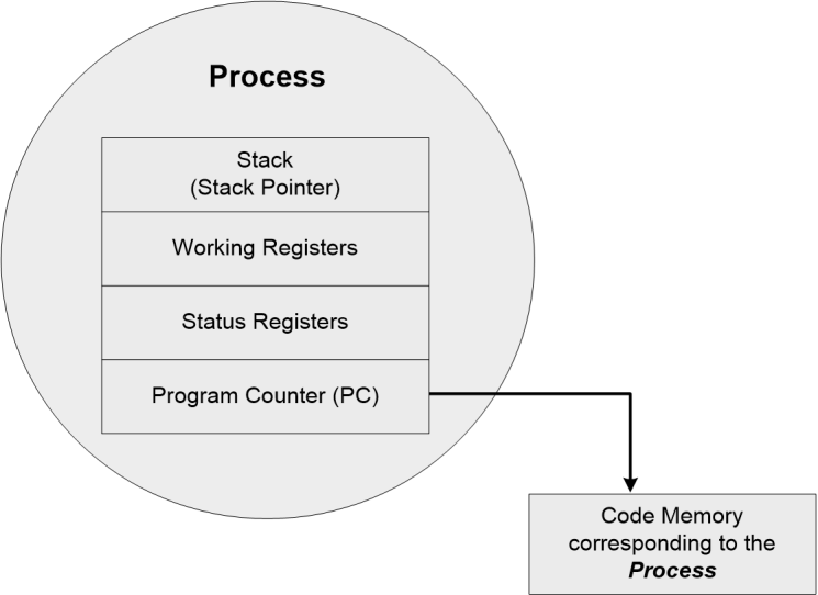
- A process mimics a processor in properties and holds a set of registers, process status, a Program Counter (PC) to point to the next executable instruction of the process, a stack for holding the local variables associated with the process and the code corresponding to the process.
- A process, which inherits all the properties of the CPU, can be considered as a virtual processor, awaiting its turn to have its properties switched into the physical processor.
- When the process gets its turn, its registers and Program counter register becomes mapped to the physical registers of the CPU.
Memory organization of a Processes
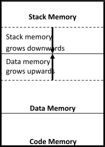
- The memory occupied by the process is segregated into three regions namely; Stack memory, Data memory and Code memory
- The ‘Stack’ memory holds all temporary data such as variables local to the process
- Data memory holds all global data for the process
- The code memory contains the program code (instructions) corresponding to the process.
- On loading a process into the main memory, a specific area of memory is allocated for the process
- The stack memory usually starts at the highest memory address from the memory area allocated for the process (Depending on the OS kernel implementation)
Process States & State Transition
- The creation of a process to its termination is not a single step operation
- The process traverses through a series of states during its transition from the newly created state to the terminated state.
- The cycle through which a process changes its state from ‘newly created’ to ‘execution completed’ is known as ‘Process Life Cycle’. The various states through which a process traverses through during a Process Life Cycle indicates the current status of the process with respect to time and also provides information on what it is allowed to do next
Created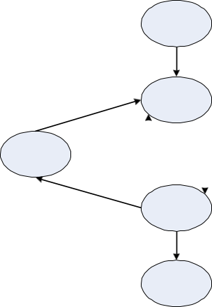
Incepted into memory
Ready


Blocked


Running

Execution Completion
Completed
- Created State: The state at which a process is being created is referred as ‘Created State’. The Operating System recognizes a process in the ‘Created State’ but no resources are allocated to the process
- Ready State: The state, where a process is incepted into the memory and awaiting the processor time for execution, is known as ‘Ready State’. At this stage, the process is placed in the ‘Ready list’ queue maintained by the OS.
- Running State: The state where in the source code instructions corresponding to the process is being executed is called ‘Running State’. Running state is the state at which the process execution happens.
- Blocked State/Wait State: Refers to a state where a running process is temporarily suspended from execution and does not have immediate access to resources. The blocked state might have invoked by various conditions like- the process enters a wait state for an event to occur (E.g. Waiting for user inputs such as keyboard input) or waiting for getting access to a shared resource like semaphore, mutex etc
- Completed State: A state where the process completes its execution
- The transition of a process from one state to another is known as ‘State transition’
- When a process changes its state from Ready to running or from running to blocked or terminated or from blocked to running, the CPU allocation for the process may also change
Threads
- A thread is the primitive that can execute code
- A thread is a single sequential flow of control within a process
- ‘Thread’ is also known as lightweight process
- A process can have many threads of execution
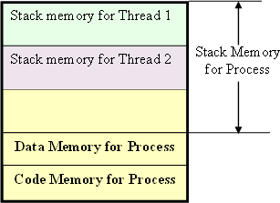
- Different threads, which are part of a process, share the same address space; meaning they share the data memory, code memory and heap memory area
- Threads maintain their own thread status (CPU register values), Program Counter (PC) and stack.
- Applications use concurrent processes to speed up their operation. However, switching between processes within an application incurs high process switching overhead because the size of the process state information is large, so operating system designers developed an alternative model of execution of a program, called a thread, that could provide concurrency within an application with less overhead.
The Concept of multithreading
Use of multiple threads to execute a process brings the following advantage.
- Better memory utilization. Multiple threads of the same process share the address space for data memory. This also reduces the complexity of inter thread communication since variables can be shared across the threads.
- Since the process is split into different threads, when one thread enters a wait state, the CPU can be utilized by other threads of the process that do not require the event, which the other thread is waiting, for processing. This speeds up the execution of the process.
- Efficient CPU utilization. The CPU is engaged all time.
Thread Standards:
Thread standards deal with the different standards available for thread creation and management. These standards are utilized by the Operating Systems for thread creation and thread management. It is a set of thread class libraries. The commonly available thread class libraries are
POSIX Threads: POSIX stands for Portable Operating System Interface. The POSIX.4 standard deals with the Real Time extensions and POSIX.4a standard deals with thread extensions. The POSIX standard library for thread creation and management is ‘Pthreads’. ‘Pthreads’ library defines the set of POSIX thread creation and management functions in ‘C’ language.
POSIX Thread Creation
int pthread_create(pthread_t *new_thread_ID, const pthread_attr_t *attribute, void * (*start_function)(void *), void *arguments);
Creates a new thread for running the function start_function. Here pthread_t is the handle to the newly created thread and pthread_attr_1 is the data type for holding the thread attributes. ‘start_function’ is the function the thread is going to execute and arguments is the arguments for start_function. On successful creation of a Pthread, pthread_create( ) associates the Thread control block (TCB) corresponding to the newly created thread to the variable of type pthread_t.
The primitive
Int pthread_join (pthread_t new_thread, void* *thread_status);
Blocks the current thread and waits until the completion of the thread pointed by it.
All the POXIS ‘thread calls’ returns an integer. A return value of zero indicates the success of the call. It is always good to check the return value of each call.
Thread pre-emption
Thread pre-emption is the act of pre-empting the currently running thread (stopping the currently running thread temporarily).
- User Level Thread: : User level threads do not have kernel/Operating System support and they exist solely in the running process. Even if a process contains multiple user level threads, the OS treats it as single thread and will not switch the execution among the different threads of it. It is the responsibility of the process to schedule each thread as and when required. In summary, user level threads of a process are non-preemptive at thread level from OS perspective.
- Kernel Level/System Level Thread: Kernel level threads are individual units of execution, which the OS treats as separate threads. The OS interrupts the execution of the currently running kernel thread and switches the execution to another kernel thread based on the scheduling policies implemented by the OS.
- The execution switching (thread context switching) of user level threads happen only when the currently executing user level thread is voluntarily blocked. Hence, no OS intervention and system calls are involved in the context switching of user level threads. This makes context switching of user level threads very fast.
- Kernel level threads involve lots of kernel overhead and involve system calls for context switching. However, kernel threads maintain a clear layer of abstraction and allow threads to use system calls independently
- Many-to-One Model: Many user level threads are mapped to a single kernel thread. The kernel treats all user level threads as single thread and the execution switching among the user level threads happens when a currently executing user level thread voluntarily blocks itself or relinquishes the CPU. Solaris Green threads and GNU Portable Threads are examples for this.
- One-to-One Model: Each user level thread is bonded to a kernel/system level thread. Windows XP/NT/2000 and Linux threads are examples of One-to-One thread models.
- Many-to-Many Model: In this model many user level threads are allowed to be mapped to many kernel threads. Windows NT/2000 with ThreadFiber package is an example for this.
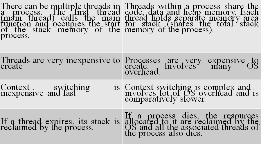
Differences between Thread V/s Process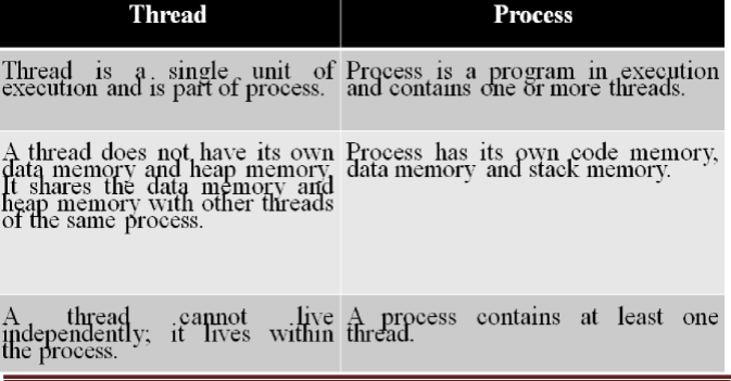
Preemptive scheduling
- Employed in systems, which implements preemptive multitasking model.
- Every task in the ‘Ready’ queue gets a chance to execute. When and how often each process gets a chance to execute (gets the CPU time) is dependent on the type of preemptive scheduling algorithm used for scheduling the processes.
- The scheduler can preempt (stop temporarily) the currently executing task/process and select another task from the ‘Ready’ queue for execution.
- When to pre-empt a task and which task is to be picked up from the ‘Ready’ queue for execution after preempting the current task is purely dependent on the scheduling algorithm.
- A task which is preempted by the scheduler is moved to the ‘Ready’ queue. The act of moving a ‘Running’ process/task into the ‘Ready’ queue by the scheduler, without the processes requesting for it is known as ‘Preemption’.
- Time-based preemption and priority-based preemption are the two important approaches adopted in preemptive scheduling.
- Preemptive SJF Scheduling/ Shortest Remaining Time (SRT)
- The non preemptive SJF scheduling algorithm sorts the ‘Ready’ queue only after the current process completes execution or enters wait state, whereas the preemptive SJF scheduling algorithm sorts the ‘Ready’ queue when a new process enters the ‘Ready’ queue and checks whether the execution time of the new process is shorter than the remaining of the total estimated execution time of the currently executing process
- If the execution time of the new process is less, the currently executing process is preempted and the new process is scheduled for execution
- Always compares the execution completion time (ie the remaining execution time for the new process) of a new process entered the ‘Ready’ queue with the remaining time for completion of the currently executing process and schedules the process with shortest remaining time for execution.
Ex 1): Three processes with process IDs P1, P2, P3 with estimated completion time 10, 5, 7 milliseconds respectively enters the ready queue together. A new process P4 with estimated completion time 2ms enters the ‘Ready’ queue after 2ms. Assume all the processes contain only CPU operation and no I/O operations are involved.
- At the beginning, there are only three processes (P1, P2 and P3) available in the ‘Ready’ queue and the SRT scheduler picks up the process with the Shortest remaining time for execution completion (In this example P2 with remaining time 5ms) for scheduling. Now process P4 with estimated execution completion time 2ms enters the ‘Ready’ queue after 2ms of start of execution of P2. The processes are re-scheduled for execution in the following order
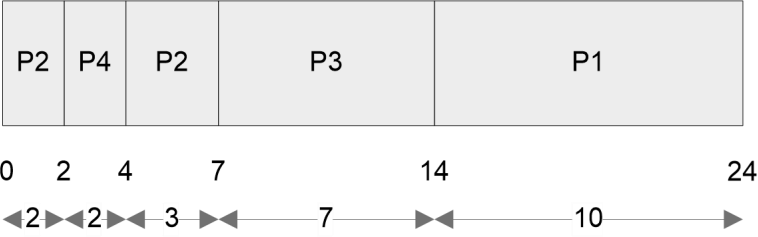
The waiting time for all the processes are given as
Waiting Time for P2 = 0 ms + (4 -2) ms = 2ms (P2 starts executing first and is interrupted by P4 and has to wait till the completion of P4 to get the next CPU slot)
Waiting Time for P4 = 0 ms (P4 starts executing by preempting P2 since the execution time for completion of P4 (2ms) is less than that of the Remaining time for execution completion of P2 (Here it is 3ms))
Waiting Time for P3 = 7 ms (P3 starts executing after completing P4 and P2) Waiting Time for P1 = 14 ms (P1 starts executing after completing P4, P2 and P3) Average waiting time = (Waiting time for all the processes) / No. of Processes
= (Waiting time for (P4+P2+P3+P1)) / 4
= (0 + 2 + 7 + 14)/4 = 23/4
= 5.75 milliseconds
Turn Around Time (TAT) for P2 = 7 ms (Time spent in Ready Queue + Execution Time)
Turn Around Time (TAT) for P4 = 2 ms (Time spent in Ready Queue + Execution Time = (Execution Start Time – Arrival Time) + Estimated Execution Time = (2-2) + 2)
Turn Around Time (TAT) for P3 = 14 ms (Time spent in Ready Queue + Execution Time) Turn Around Time (TAT) for P1 = 24 ms (Time spent in Ready Queue + Execution Time)
Average Turn Around Time = (Turn Around Time for all the processes) / No. of Processes
= (Turn Around Time for (P2+P4+P3+P1)) / 4
= (7+2+14+24)/4 = 47/4
= 11.75 milliseconds
- Round Robin (RR) Scheduling:
- Each process in the ‘Ready’ queue is executed for a pre-defined time slot.
- The execution starts with picking up the first process in the ‘Ready’ queue. It is executed for a pre- defined time
- When the pre-defined time elapses or the process completes (before the pre-defined time slice), the next process in the ‘Ready’ queue is selected for execution.
- This is repeated for all the processes in the ‘Ready’ queue
- Once each process in the ‘Ready’ queue is executed for the pre-defined time period, the scheduler comes back and picks the first process in the ‘Ready’ queue again for execution.
- Round Robin scheduling is similar to the FCFS scheduling and the only difference is that a time slice based preemption is added to switch the execution between the processes in the ‘Ready’ queue
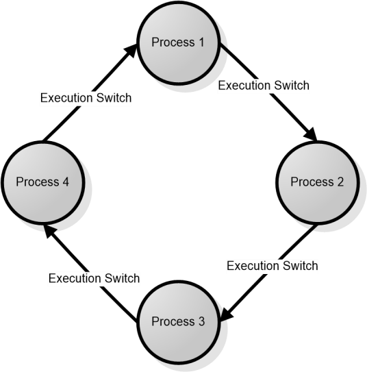
Ex 2): Three processes with process IDs P1, P2, P3 with estimated completion time 6, 4, 2 milliseconds respectively, enters the ready queue together in the order P1, P2, P3. Calculate the waiting time and Turn Around Time (TAT) for each process and the Average waiting time and Turn Around Time (Assuming there is no I/O waiting for the processes) in RR algorithm with Time slice= 2ms.
- The scheduler sorts the ‘Ready’ queue based on the FCFS policy and picks up the first process P1 from the ‘Ready’ queue and executes it for the time slice 2ms. When the time slice is expired, P1 is preempted and P2 is scheduled for execution. The Time slice expires after 2ms of execution of P2. Now P2 is preempted and P3 is picked up for execution. P3 completes its execution within the time slice and the scheduler picks P1 again for execution for the next time slice. This procedure is repeated till all the processes are serviced. The order in which the processes are scheduled for execution is represented as
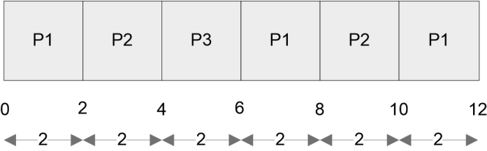
The waiting time for all the processes are given as
Waiting Time for P1 = 0 + (6-2) + (10-8) = 0+4+2= 6ms (P1 starts executing first and waits for two time slices to get execution back and again 1 time slice for getting CPU time)
Waiting Time for P2 = (2-0) + (8-4) = 2+4 = 6ms (P2 starts executing after P1 executes for 1 time slice and waits for two time slices to get the CPU time)
Waiting Time for P3 = (4 -0) = 4ms (P3 starts executing after completing the first time slices for P1 and P2 and completes its execution in a single time slice.)
Average waiting time = (Waiting time for all the processes) / No. of Processes
= (Waiting time for (P1+P2+P3)) / 3
= (6+6+4)/3 = 16/3
= 5.33 milliseconds
Turn Around Time (TAT) for P1 = 12 ms (Time spent in Ready Queue + Execution Time) Turn Around Time (TAT) for P2 = 10 ms (-Do-)
Turn Around Time (TAT) for P3 = 6 ms (-Do-)
Average Turn Around Time = (Turn Around Time for all the processes) / No. of Processes
= (Turn Around Time for (P1+P2+P3)) / 3
= (12+10+6)/3 = 28/3
= 9.33 milliseconds
- Priority based Scheduling
- Same as that of the non-preemptive priority based scheduling except for the switching of execution between tasks
- In preemptive priority based scheduling, any high priority process entering the ‘Ready’ queue is immediately scheduled for execution whereas in the non-preemptive scheduling any high priority process entering the ‘Ready’ queue is scheduled only after the currently executing process completes its execution or only when it voluntarily releases the CPU
- The priority of a task/process in preemptive priority based scheduling is indicated in the same way as that of the mechanisms adopted for non-preemptive multitasking.
Ex 3): Three processes with process IDs P1, P2, P3 with estimated completion time 10, 5, 7 milliseconds and priorities 1, 3, 2 (0- highest priority, 3 lowest priority) respectively enters the ready queue together. A new process P4 with estimated completion time 6ms and priority 0 enters the ‘Ready’ queue after 5ms of start of execution of P1. Assume all the processes contain only CPU operation and no I/O operations are involved.
- At the beginning, there are only three processes (P1, P2 and P3) available in the ‘Ready’ queue and the scheduler picks up the process with the highest priority (In this example P1 with priority 1) for scheduling. Now process P4 with estimated execution completion time 6ms and priority 0 enters the ‘Ready’ queue after 5ms of start of execution of P1. The processes are re-scheduled for execution in the following order
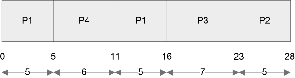
The waiting time for all the processes are given as
Waiting Time for P1 = 0 + (11-5) = 0+6 =6 ms (P1 starts executing first and gets preempted by P4 after 5ms and again gets the CPU time after completion of P4)
Waiting Time for P4 = 0 ms (P4 starts executing immediately on entering the ‘Ready’ queue, by preempting P1)
Waiting Time for P3 = 16 ms (P3 starts executing after completing P1 and P4) Waiting Time for P2 = 23 ms (P2 starts executing after completing P1, P4 and P3) Average waiting time = (Waiting time for all the processes) / No. of Processes
= (Waiting time for (P1+P4+P3+P2)) / 4
= (6 + 0 + 16 + 23)/4 = 45/4
= 11.25 milliseconds
Turn Around Time (TAT) for P1 = 16 ms (Time spent in Ready Queue + Execution Time)
Turn Around Time (TAT) for P4 = 6ms (Time spent in Ready Queue + Execution Time = (Execution Start Time – Arrival Time) + Estimated Execution Time = (5-5) + 6 = 0 + 6)
Turn Around Time (TAT) for P3 = 23 ms (Time spent in Ready Queue + Execution Time) Turn Around Time (TAT) for P2 = 28 ms (Time spent in Ready Queue + Execution Time) Average Turn Around Time = (Turn Around Time for all the processes) / No. of Processes
= (Turn Around Time for (P2+P4+P3+P1)) / 4
= (16+6+23+28)/4 = 73/4
= 18.25 milliseconds
Task Communication:
In a multitasking system, multiple tasks/processes run concurrently (in pseudo parallelism) and each process may or may not interact between. Based on the degree of interaction, the processes /tasks running on an OS are classified as
- Co-operating Processes: In the co-operating interaction model one process requires the inputs from other processes to complete its execution.
- Competing Processes: The competing processes do not share anything among themselves but they share the system resources. The competing processes compete for the system resources such as file, display device etc
The co-operating processes exchanges information and communicate through
- Co-operation through sharing: Exchange data through some shared resources.
- Co-operation through Communication: No data is shared between the processes. But they communicate for execution synchronization.
Inter Process (Task) Communication (IPC)
- IPC refers to the mechanism through which tasks/processes communicate each other
- IPC is essential for task /process execution co-ordination and synchronization
- Implementation of IPC mechanism is OS kernel dependent
- Some important IPC mechanisms adopted by OS kernels are:
- Pipes (Named & Un-named)
- Memory mapped Objects
- Message Queues
- Mailbox
- Signals
- Remote Procedure Calls (RPC)
Shared Memory
- Processes share some area of the memory to communicate among them
- Information to be communicated by the process is written to the shared memory area
- Processes which require this information can read the same from the shared memory area
- Same as the real world concept where a ‘Notice Board’ is used by the college to publish the information for students (The only exception is; only college has the right to modify the information published on the Notice board and students are given ‘Read’ only access. Meaning it is only a one way channel)
Pipes:
‘Pipe’ is a section of the shared memory used by processes for communicating. Pipes follow the client-server architecture. A process which creates a pipe is known as pipe server and a process which connects to a pipe is known as pipe client. A pipe can be considered as a conduit for information flow and has two conceptual ends. It can be unidirectional, allowing information flow in one direction or bidirectional allowing bi- directional information flow. A unidirectional pipe allows the process connecting at one end of the pipe to write to the pipe and the process connected at the other end of the pipe to read the data, whereas a bi- directional pipe allows both reading and writing at one end.
Process 1 Write
Process 2 Read
The implementation of ‘Pipes’ is OS dependent. Microsoft® Windows Desktop Operating Systems support two types of ‘Pipes’ for Inter Process Communication. Namely;
Anonymous Pipes: The anonymous pipes are unnamed, unidirectional pipes used for data transfer between two processes.
Named Pipes: Named pipe is a named, unidirectional or bi-directional pipe for data exchange between processes. Like anonymous pipes, the process which creates the named pipe is known as pipe server. A process which connects to the named pipe is known as pipe client. With named pipes, any process can act as both client and server allowing point-to-point communication. Named pipes can be used for communicating between processes running on the same machine or between processes running on different machines connected to a network.
Memory Mapped Objects:
- A shared memory technique adopted by certain Real Time Operating Systems for allocating a shared block of memory which can be accessed by multiple process simultaneously (of course certain synchronization techniques should be applied to prevent inconsistent results).
- A mapping object is created and physical storage for it is reserved and committed.
- A process can map the entire committed physical area or a block of it to its virtual address space
- All read and write operation to this virtual address space by a process is directed to its committed physical area
- Any process which wants to share data with other processes can map the physical memory area of the mapped object to its virtual memory space and use it for sharing the data.
Message Passing
- A synchronous/asynchronous information exchange mechanism for Inter Process/ thread Communication
- Through shared memory lot of data can be shared whereas only limited amount of info/data is passed through message passing
- Message passing is relatively fast and free from the synchronization overheads compared to shared memory.
Message Queues:
- Process which wants to talk to another process posts the message to a First-In-First-Out (FIFO) queue called ‘Message queue’, which stores the messages temporarily in a system defined memory object, to pass it to the desired process.
- Messages are sent and received through send (Name of the process to which the message is to be sent, message) and receive (Name of the process from which the message is to be received, message) methods
- The messages are exchanged through a message queue
- The implementation of the message queue, send and receive methods are OS kernel dependent.
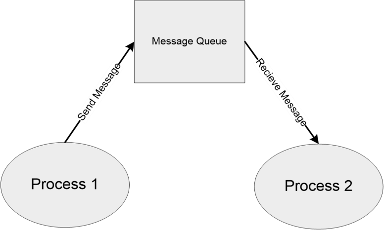
Concept of Message Queue
Mailbox:
- A special implementation of message queue.
- Usually used for one way communication.
- Only a single message is exchanged through mailbox whereas ‘message queue’ can be used for exchanging multiple messages.
- One task/process creates the mailbox and other tasks/process can subscribe to this mailbox for getting message notification.
- The implementation of the mailbox is OS kernel dependent.
- The MicroC/OS-II RTOS implements mailbox as a mechanism for inter task communication.
-
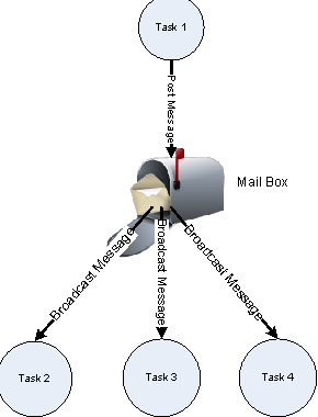
- Signal:
- An asynchronous notification mechanism
- Mainly used for the execution synchronization of tasks process/tasks
- Signal do not carry any data and are not queued
- The implementation of signals is OS kernel dependent
- VxWorks RTOS kernel implements ‘signals’ for inter process communication
- A task/process can create a set of signals and register for it
- A task or Interrupt Service Routine (ISR) can signal a ‘signal’
- Whenever a specified signal occurs it is handled in a signal handler associated with the signal.
Remote Procedure Call (RPC)
- The IPC mechanism used by a process to call a procedure of another process running on the same CPU or on a different CPU which is interconnected in a network.
- In the object oriented language terminology RPC is also known as Remote Invocation or Remote Method Invocation (RMI) .
- RPC is mainly used for distributed applications like client-server applications.
- With RPC it is possible to communicate over a heterogeneous network (i.e. Network where Client and server applications are running on different Operating systems).
- The CPU/Process containing the procedure which needs to be invoked remotely is known as server.
- The CPU/Process which initiates an RPC request is known as client.
- In order to make the RPC communication compatible across all platforms it should stick on to certain standard formats.
- Interface Definition Language (IDL) defines the interfaces for RPC.
- Microsoft Interface Definition Language (MIDL) is the IDL implementation from Microsoft for all Microsoft platforms.
- The RPC communication can be either Synchronous (Blocking) or Asynchronous (Non-blocking)
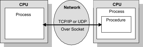
Processes running on different CPUs which are networked
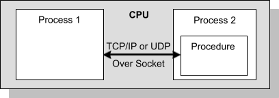
Processes running on same CPU
Concept of Remote Procedure Call (RPC) for IPC
- RPC uses sockets for implementing communication.
- Socket is a logical endpoint in a two-way communication link between two applications running on a network.
- A port number is associated with a socket so that the network layer of the communication channel can deliver the data to the designated application.
- Sockets are of different types namely; Internet sockets (INET), UNIX sockets etc.
- The INET Socket works on Internet Communication protocol. TCP/IP, UDP etc are the communication protocols used by INET sockets.
- INET sockets are classified into:
- Stream Sockets
- Datagram Sockets
Stream sockets are connection oriented and they use TCP to establish a reliable connection. Datagram Sockets rely on UDP for establishing a connection.
Task Synchronization
- Multiple processes may try to access and modify shared resources in a multitasking environment. This may lead to conflicts and inconsistent results.
- Processes should be made aware of the access of a shared resource by each process and should not be allowed to access a shared resource when it is currently being accessed by other processes.
- The act of making processes aware of the access of shared resources by each process to avoid conflicts is known as ‘Task/Process Synchronization’.
- Task Synchronization is essential for avoiding conflicts in shared resource access and ensuring a specified sequence for task execution.
- Various synchronization issues may arise in a multitasking environment if processes are not synchronized properly in shared resource access.
Task Synchronization Issues – Racing
Have a look at the following piece of code
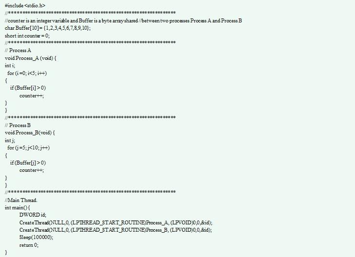
From a programmer perspective, the value of counter will be 10 at the end of execution of processes A & B. But it need not be always. program statement counter++; looks like a single statement from a high level programming language (C Language) perspective. The low level implementation of this statement is dependent on the underlying processor instruction set and the (cross) compiler in use. The low level implementation of the high level program statement counter++; under Windows XP operating system running on an Intel Centrino Duo processor is given below. The code snippet is compiled with Microsoft Visual Studio 6.0 compiler.

At the processor instruction level, the value of the variable counter is loaded to the Accumulator register (EAX Register). The memory variable counter is represented using a pointer. The base pointer register (EBP Register) is used for pointing to the memory variable counter. After loading the contents of the variable counter to the Accumulator, the Accumulator content is incremented by one using the add instruction. Finally the content of Accumulator is loaded to the memory location which represents the variable counter. Both the processes Process A and Process B contain the program statement counter++; Translating this into the machine instruction.
Process A | Process B |
mov eax,dword ptr [ebp-4] add eax,1 mov dword ptr [ebp-4],eax | mov eax,dword ptr [ebp-4] add eax,1 mov dword ptr [ebp-4],eax |
Imagine a situation where a process switching (context switching) happens from Process A to Process B when Process A is executing the counter++; statement. Process A accomplishes the counter++; statement through three different low level instructions. Now imagine that the process switching happened at the point where Process A executed the low level instruction mov eax,dword ptr [ebp-4] and is about to execute the next instruction add eax,1. The scenario is illustrated below.
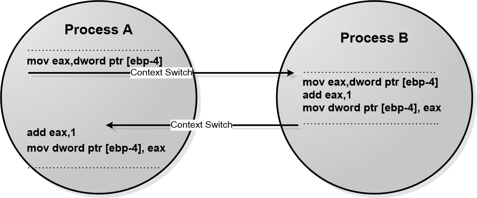
Process B increments the shared variable ‘counter’ in the middle of the operation where Process A tries to increment it. When Process A gets the CPU time for execution, it starts from the point where it got interrupted (If Process B is also using the same registers eax and ebp for executing counter++; instruction, the original content of these registers will be saved (PUSHed) by Process B before using it and the contents will be retrieved (POPed) after finishing the operation. Hence the content of eax and ebp remains intact irrespective of context switching). Though the variable counter is incremented by Process B, Process A is unaware of it and it increments the variable with the old value. This leads to the loss of one increment for the variable counter.
Task Synchronization Issues – Deadlock
Deadlock is the condition in which a process is waiting for a resource held by another process which is waiting for a resource held by the first process. Process A holds a resource ‘x’ and it wants a resource ‘y’ held by Process B. Process B is currently holding resource ‘y’ and it wants the resource ‘x’ which is currently held by Process A. Both hold the respective resources and they compete each other to get the resource held by the respective processes.
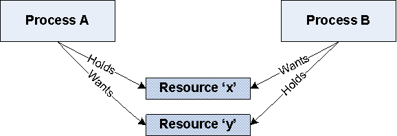

Mutual Exclusion: The criteria that only one process can hold a resource at a time. Meaning processes should access shared resources with mutual exclusion. Typical example is the accessing of display device in an embedded device
Hold & Wait: The condition in which a process holds a shared resource by acquiring the lock controlling the shared access and waiting for additional resources held by other processes
No Resource Preemption: The criteria that Operating System cannot take back a resource from a process which is currently holding it and the resource can only be released voluntarily by the process holding it.
Circular Wait: A process is waiting for a resource which is currently held by another process which in turn is waiting for a resource held by the first process. In general there exists a set of waiting process P0, P1 …. Pn with P0 is waiting for a resource held by P1 and P1 is waiting for a resource held by P0, ……, Pn is waiting for a resource held by P0 and P0 is waiting for a resource held by Pn and so on… This forms a circular wait queue.
‘Deadlock’ is a result of the combined occurrence of these four conditions listed above. These conditions are first described by E. G. Coffman in 1971 and it is popularly known as Coffman conditions.
A smart OS may foresee the deadlock condition and will act proactively to avoid such a situation. Now if a deadlock occurred, how the OS responds to it? The reaction to deadlock condition by OS is non uniform. The OS may adopt any of the following techniques to detect and prevent deadlock conditions.
Ignore Deadlocks: Always assume that the system design is deadlock free. This is acceptable for the reason the cost of removing a deadlock is large compared to the chance of happening a deadlock. UNIX is an example for an OS following this principle. A life critical system cannot pretend that it is deadlock free for any reason.
Detect and Recover: This approach suggests the detection of a deadlock situation and recovery from it. This is similar to the deadlock condition that may arise at a traffic junction. When the vehicles from different directions compete to cross the junction, deadlock (traffic jam) condition is resulted. Once a deadlock (traffic jam) is happened at the junction, the only solution is to back up the vehicles from one direction and allow the vehicles from opposite direction to cross the junction. If the traffic is too high, lots of vehicles may have to be backed up to resolve the traffic jam. This technique is also known as ‘back up cars’ technique
Operating Systems keep a resource graph in their memory. The resource graph is updated on each resource request and release. A deadlock condition can be detected by analyzing the resource graph by graph analyzer algorithms. Once a deadlock condition is detected, the system can terminate a process or preempt the resource to break the deadlocking cycle.
Avoid Deadlocks: Deadlock is avoided by the careful resource allocation techniques by the Operating System. It is similar to the traffic light mechanism at junctions to avoid the traffic jams.
Prevent Deadlocks: Prevent the deadlock condition by negating one of the four conditions favoring the deadlock situation.
- Ensure that a process does not hold any other resources when it requests a resource. This can be achieved by implementing the following set of rules/guidelines in allocating resources to processes
- A process must request all its required resource and the resources should be allocated before the process begins its execution.
- Grant resource allocation requests from processes only if the process does not hold a resource currently
- Ensure that resource preemption (resource releasing) is possible at operating system level. This can be achieved by implementing the following set of rules/guidelines in resources allocation and releasing
- Release all the resources currently held by a process if a request made by the process for a new resource is not able to fulfill immediately.
- Add the resources which are preempted (released) to a resource list describing the resources which the process requires to complete its execution.
- Reschedule the process for execution only when the process gets its old resources and the new resource which is requested by the process.
Livelock: The Livelock condition is similar to the deadlock condition except that a process in livelock condition changes its state with time. While in deadlock a process enters in wait state for a resource and continues in that state forever without making any progress in the execution. In a livelock condition a process always do something but unable to make any progress in the execution completion. The livelock condition is better explained with the real world example, two people attempting to cross each other in a narrow corridor. Both of the persons move towards each side of the corridor to allow the opposite person to cross. Since the corridor is narrow, none of them are able to cross each other. Here both of the persons perform some action but still they are unable to achieve their target- Cross each other.
Starvation: In the task synchronization issue context, starvation is the condition in which a process does not get the resources required to continue its execution for a long time. As time progresses the process starves on resource. Starvation may arise due to various conditions like byproduct of preventive measures of deadlock, scheduling policies favoring high priority tasks and tasks with shortest execution time etc.
Integration and Testing of Embedded hardware and Firmware:
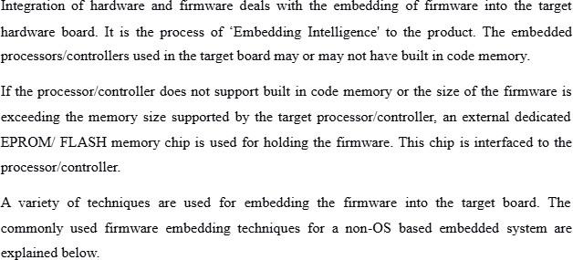
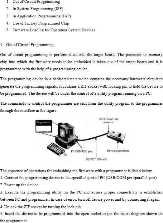
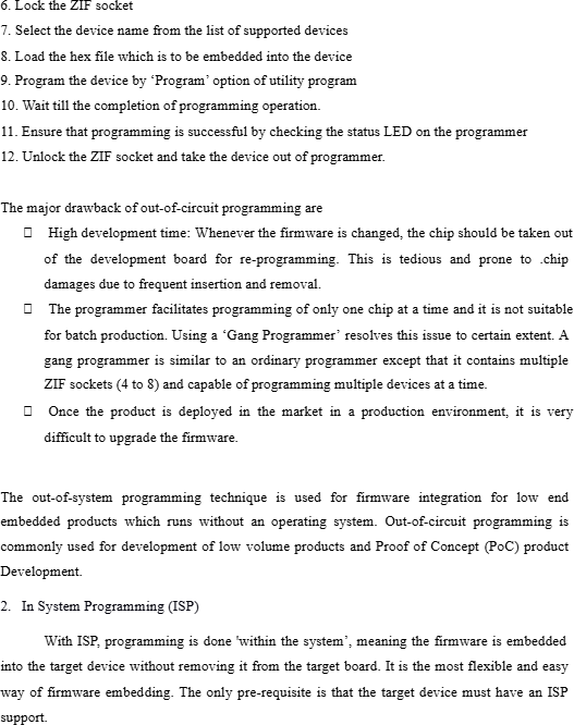
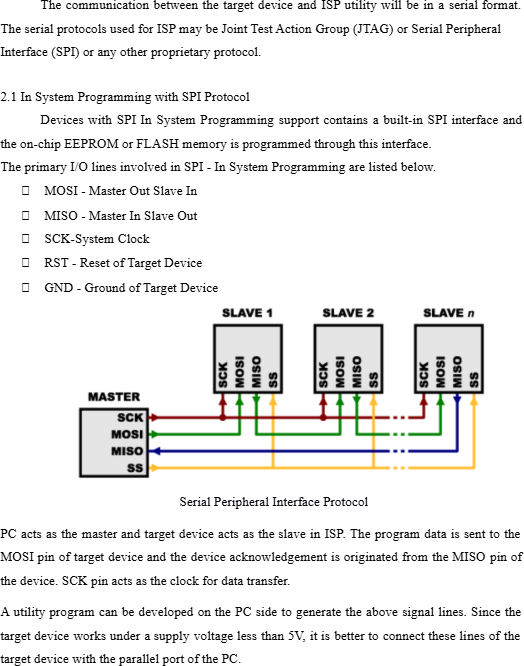
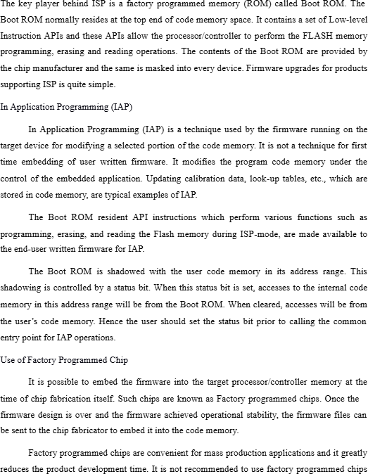
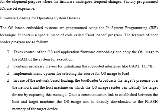
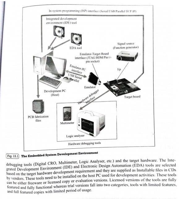
The Embedded System Development Environment:
The Development Environment consists of a Development computer (PC) or host, which acts as the heart of the development environment, Integrated Development Environment (IDE) tool for embedded firmware development and debugging, Electronic Design Automation (EDA)tool for Embedded Hardware design. An emulator hardware for debugging the target board, Signal sources (like function generator0 for simulating the inputs to the target board, Target hardware